
- Published on
Transformer Vector Groups Explained: Dyn1, Dyn11, and Why It Matters
- Authors

- Name
- Ben Gibb
TL;DR — Transformer vector groups describe the winding configuration and phase displacement between primary and secondary windings. A Dyn1 has the secondary lagging by 30°, while a Dyn11 has the secondary leading by 30°—a 60° difference. If your transformer operates in isolation, this substitution likely doesn't matter. If you need to parallel transformers or synchronize with other sources, it's a showstopper.
The backstory...
Vector groups are one of those transformer specifications that often get glossed over until something goes wrong. The naming convention packs a lot of information into a short code, and understanding it can save you from a costly mistake—or help you realize when a procurement mix-up isn't actually a problem.
Let's break down what Dyn1 and Dyn11 mean and why the difference matters.
What does the vector group designation tell us?
The vector group is a three-part code: the HV winding configuration, the LV winding configuration, and the phase displacement.
- D = Delta-connected primary (HV side)
- y = Star (wye) connected secondary (LV side)
- n = Neutral brought out on the secondary
- Number = Phase displacement using the clock-face convention
The clock convention is intuitive once you see it. Picture the HV phase voltage as the minute hand pointing to 12 o'clock. The number in the vector group tells you where the LV phase voltage points on the clock face. Each hour represents 30 degrees.
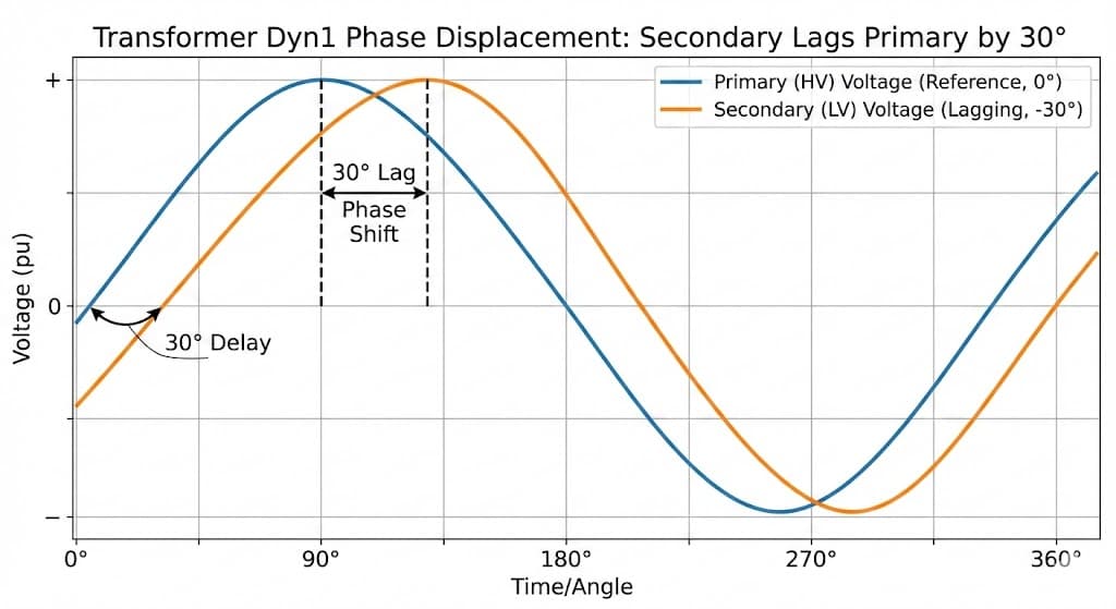
For Dyn1, the secondary voltage vector points to 1 o'clock, meaning the LV lags the HV by 30°. For Dyn11, the secondary points to 11 o'clock, meaning the LV leads the HV by 30° (or equivalently, lags by 330°).
The difference between these two? A full 60 degrees of angular displacement.
If LV leads HV, the LV waveform is shifted left on a time-domain plot. Leading means the LV reaches its peak before the HV does. Time moves left to right, so "before" = further left. So for Dyn11 where LV leads by 30°, you'd see the LV sine wave shifted left of the HV reference. For Dyn1 where LV lags by 30°, the LV waveform shifts right.
So, does it matter if I received Dyn11 instead of Dyn1?
It depends entirely on your application. There are two scenarios to consider.
Scenario 1: Standalone transformer feeding an isolated load
If your transformer feeds a load that has no need to synchronize or parallel with other sources, you're likely fine. The transformer will step down (or up) voltage, provide three-phase power, and give you a solid neutral reference. The 60° phase shift relative to the incoming supply doesn't affect the downstream load—it simply establishes a new phase reference for everything connected to the secondary.
In this case, the Dyn11 will work just as well as the Dyn1. Accept the substitution and move on.
Scenario 2: Paralleling or synchronizing with other sources
This is where the vector group mismatch becomes critical. Paralleling transformers requires that the secondary voltages are in phase with each other. A 60° displacement between a Dyn1 and Dyn11 will result in a voltage difference across the paralleling connection, driving massive circulating currents. This will trip protection at best and damage equipment at worst.
Similarly, if your system has generators or other transformers already referenced to a Dyn1 phase angle, introducing a Dyn11 will throw off synchronization. Protection schemes, metering, and power flow calculations all assume a specific phase relationship. A 60° error propagates through everything.
Before accepting the substitution, ask yourself:
- Will this transformer ever be paralleled with another unit?
- Are there generators or other sources on the secondary bus?
- Does your protection or metering scheme rely on a specific phase reference relative to the primary supply?
If the answer to all three is no, the Dyn11 is functionally equivalent to the Dyn1 for your application.
If any answer is yes, you need to either return the transformer for the correct vector group, or redesign your system to accommodate the new phase reference—which is rarely practical.
Tip: When specifying transformers for facilities where future expansion might include paralleling or generator additions, document the vector group clearly in your facility standards. A Dyn11 ordered today that works fine in isolation becomes a problem five years later when someone tries to add a second unit without checking the existing installation.
The bottom line:
Vector group mismatches are either a non-issue or a dealbreaker—there's not much in between. The key is understanding your system topology. Isolated loads are forgiving. Paralleled sources are not.